Anne Reinarz Durham University
Recap: Dynamic Channel Allocations
Recap: Dynamic Channel Allocations
- Random Access Protocols
- E.g. ALOHA, CSMA, CSMA/CD
- Controlled Access Protocols
- E.g. Bitmap, Token Passing, Binary Countdown
Outline
stream of bits
### Link
Individual Bit flips/ number of bits might change
 </img>
---
# Framing Methods
- Byte count
- Flag bytes with byte stuffing
- Flag bits with bit stuffing
---
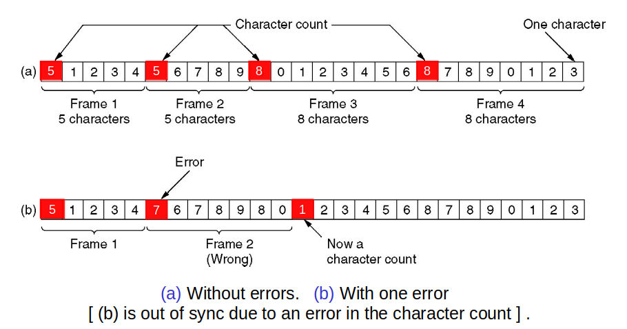
# Framing: Byte count
- Frame begins with a count of the number of bytes in it
- Simple, but difficult to resynchronize after an error
</img>
---
# Framing Methods
- Byte count
- Flag bytes with byte stuffing
- Flag bits with bit stuffing
---
# Framing: Byte count
- Frame begins with a count of the number of bytes in it
- Simple, but difficult to resynchronize after an error
 </img>
---
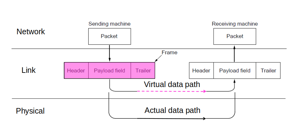
# Data Framing – Headers and Trailers
- We add a header (e.g. the length of data, etc.) and a trailer (extra data that can be used for e.g. error-detection or error-correction).
</img>
---
# Data Framing – Headers and Trailers
- We add a header (e.g. the length of data, etc.) and a trailer (extra data that can be used for e.g. error-detection or error-correction).</br>
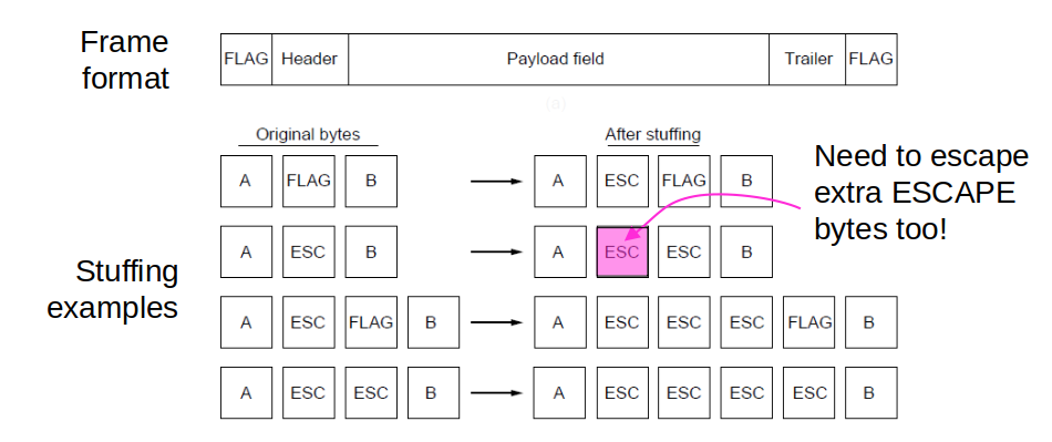
### Open Question: What happens if the flag value is found (i.e. naturally occurs) in the data? --- # Framing: Byte stuffing - Special flag bytes delimit frames; occurrences of flags in the data must be stuffed (escaped) - Longer, but easy to resynchronize after error
 </img>
---
# Framing: Byte stuffing
</img>
---
# Framing: Byte stuffing
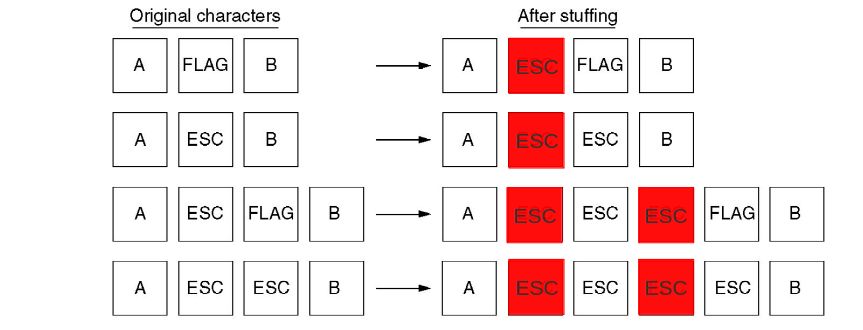 </img>
- Byte sequences before and after stuffing for a different special byte - escape!
---
# Framing: bit stuffing
</img>
- Byte sequences before and after stuffing for a different special byte - escape!
---
# Framing: bit stuffing
 </img>
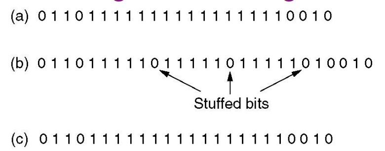
- The flag is six consecutive ones.
Within the data, a zero is stuffed after each five consecutive ones to void instances of the flag in the data.
</img>
- The flag is six consecutive ones.
Within the data, a zero is stuffed after each five consecutive ones to void instances of the flag in the data.
- The original data
- The data as they appear on the line
- The data as stored by receiver after de-stuffing
</img>
### Sender:
- encloses packet (bit stream) with flag: 0 1 1 1 1 1 1 0
- appends a 0 after each 1 1 1 1 1 in body (bit stuffing)
---
# Framing: bit stuffing
</img>
### Receiver, upon receiving 0 1 1 1 1 1:
- next bit 0: stuffed bit is removed
- next bit 1:
- if next bit 0 (i.e. 0 1 1 1 1 1 1 0): end of frame marker
- if next bit 1 (i.e. 0 1 1 1 1 1 1 1): error
---
# Error Detection and Correction (EDC)
### Errors occur during frame transmission
### Two strategies to deal with error:
1. Include enough redundant information to help receivers deduce original data (error correcting)
2. Include enough information to deduce an error occurred (error detecting)
- Neither error-correcting codes nor error-detecting codes can handle all possible errors
---
# Error Detection and Correction
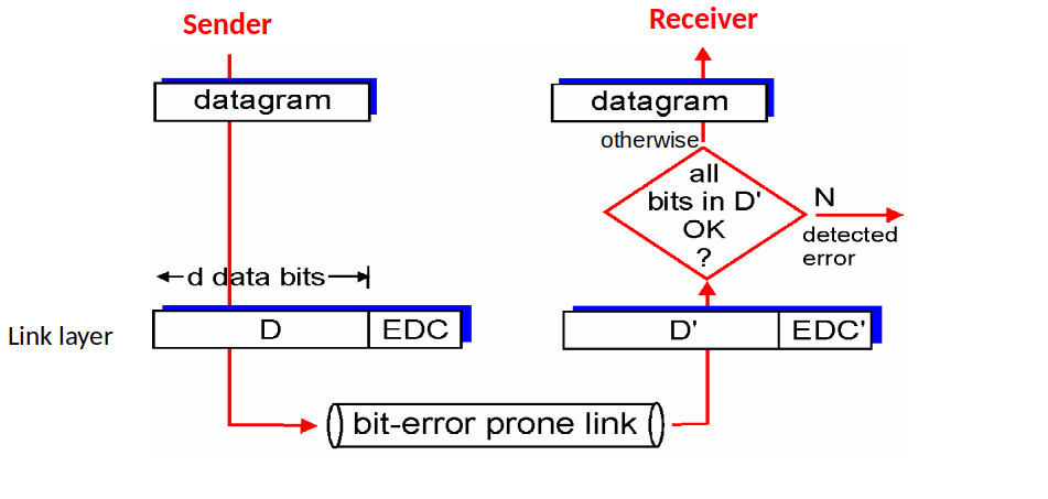
- EDC = Error Detection and Correction bits
- D = Data protected by error checking, may include header fields
 </img>
---
# Error Detection and Correction
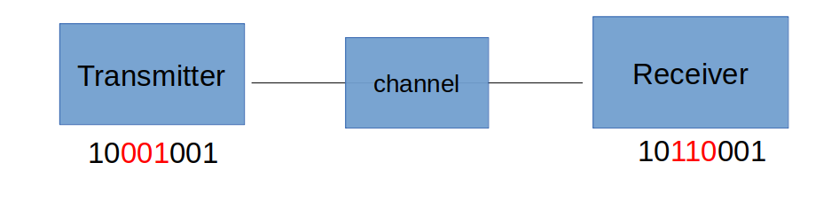
- Error detection not 100% reliable:
- a protocol may miss some errors, but rarely
### Example
</img>
---
# Error Detection and Correction
- Error detection not 100% reliable:
- a protocol may miss some errors, but rarely
### Example
 </img>
---
# Codewords
- A frame consists of m data (message) bits and r redundant (check) bits.
- n-bit codewords with n =m+r
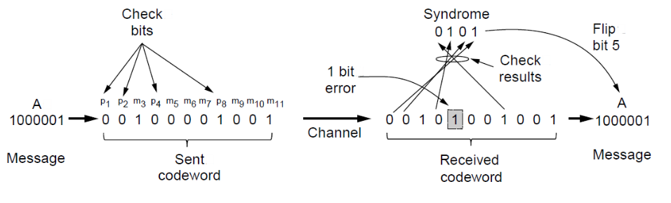
- ASCII code for “A”: 1000001
- codeword for “A”: 10000010 (r=1)
---
# Error Bounds – Hamming distance
</img>
---
# Codewords
- A frame consists of m data (message) bits and r redundant (check) bits.
- n-bit codewords with n =m+r
- ASCII code for “A”: 1000001
- codeword for “A”: 10000010 (r=1)
---
# Error Bounds – Hamming distance
 </img>
---
# Error Correction – Hamming code
</img>
---
# Error Correction – Hamming code
0 0 1 0 0 0 0 1 0 0 1 (original codeword)
0 0 1 0 1 0 0 1 0 0 1 (received codeword)
--- # Error Correction – Hamming code0 0 1 0 0 0 0 1 0 0 1 (original codeword)
- step #1: number the bits1 2 3 4 5 6 7 8 9 10 11
0 0 1 0 1 0 0 1 0 0   1  (received codeword)
--- # Error Correction – Hamming code0 0 1 0 0 0 0 1 0 0 1 (original codeword)
- step #2: allocate parity bits and message bits- powers of 2 bits are parity bits and the rest are message bitsp1 p2 m3 p4 m5 m6 m7 p8 m9 m10 m11
0   0   1     0     1    0    0    1    0    0       1     (received codeword)
--- # Error Correction – Hamming code0 0 1 0 0 0 0 1 0 0 1 (original codeword)
- step #3: finding the parity bitsp1 p2 m3 p4 m5 m6 m7 p8 m9 m10 m11
0   0   1     0     1    0    0    1    0    0       1    
- Finding p1: - Count one bit and skip one, starting from p1 but not including p1 value. - Add the 1s. If the result is even then p1 parity is 0, if the result is odd then p1 parity is 1. - p1 is? 1 1 0 0 1 → 1 --- # Error Correction – Hamming code0 0 1 0 0 0 0 1 0 0 1 (original codeword)
- step #3: finding the parity bitsp1 p2 m3 p4 m5 m6 m7 p8 m9 m10 m11
0   0   1     0     1    0    0    1    0    0       1    
- Finding p2: - Count two bits and skip two, starting from p2 but not including p2 value. - Add up the result. If the result is even then p2 parity is 0, if the result is odd then p2 parity is 1 - p2 is? 1 0 0 0 1 → 0 --- # Error Correction – Hamming code0 0 1 0 0 0 0 1 0 0 1 (original codeword)
- step #3: finding the parity bitsp1 p2 m3 p4 m5 m6 m7 p8 m9 m10 m11
0   0   1     0     1    0    0    1    0    0       1    
- Finding p4: - Count four bits and skip four, starting from p4 but not including p4 value. - Add up the result. If the result is even then p4 parity is 0, if the result is odd then p4 parity is 1. - p4 is ? 1 0 0 - - → 1 --- # Error Correction – Hamming code0 0 1 0 0 0 0 1 0 0 1 (original codeword)
- step #3: finding the parity bitsp1 p2 m3 p4 m5 m6 m7 p8 m9 m10 m11
0   0   1     0     1    0    0    1    0    0       1    
- Finding p8: - Count eight bits and skip eight, starting from p8 but not including p8 value. - Add up the result. If the result is even then p8 parity is 0, if the result is odd then p8 parity is 1. - p8 is ? 0 0 1 - - → 1 --- # Error Correction – Hamming code0 0 1 0 0 0 0 1 0 0 1 (original codeword)
- step #4: compare our result with the received parity bits.0   0   1     0     1    0    0    1    0    0       1    
- p1 is 0 1 1 0 0 1 → 1 ✘ - p2 is 0 1 0 0 0 1 → 0 ✔ - p4 is 0 1 0 0 - - → 1 ✘ - p8 is 1 0 0 1 - - → 1 ✔ - p1+p4 → in position 5 --- # Error Detection ### Three types of error detection codes: 1. Parity 2. Checksums 3. Cyclic redundancy codes --- # Error Detection – Parity - Parity bit is added as the modulo 2 sum of data bits - Equivalent to XOR; this is an odd parity - Ex: 1100110 → 11001101 - Detection checks if the sum is wrong (an error) --- # Error Detection – Parity - A sends a packet of 8 bits to B - 1 bit (the third bit) is flipped from 0 to 1 due to some noise or interference in the channel - How can we detect that the bit is flipped?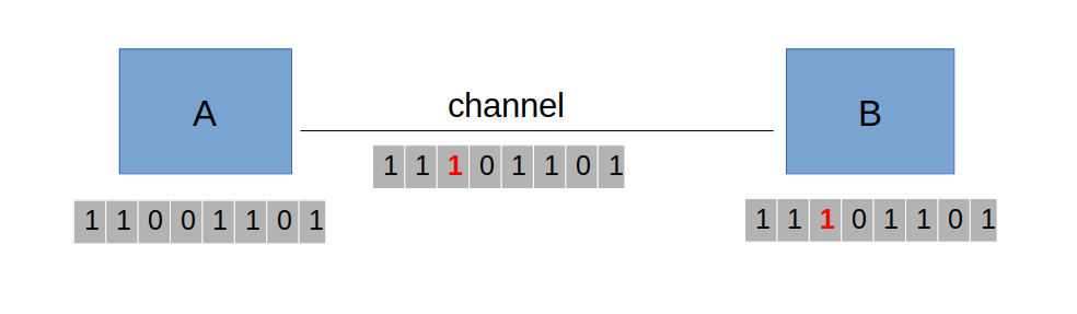 </img>
---
# Error Detection – Parity
- Parity is used to detect the error by appending a “parity bit” to the data.
- Example: A protocol between two hosts using odd parity for error detection
</img>
---
# Error Detection – Parity
- Parity is used to detect the error by appending a “parity bit” to the data.
- Example: A protocol between two hosts using odd parity for error detection
 </img>
---
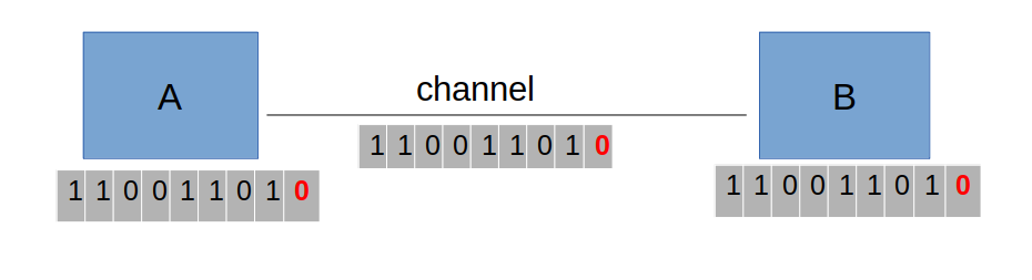
# Error Detection – Parity
- Parity is used to detect the error by appending a “parity bit” to the data.
- Example: A protocol between two hosts using even parity for error detection
</img>
---
# Error Detection – Parity
- Parity is used to detect the error by appending a “parity bit” to the data.
- Example: A protocol between two hosts using even parity for error detection
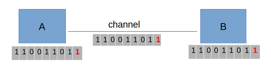 </img>
---
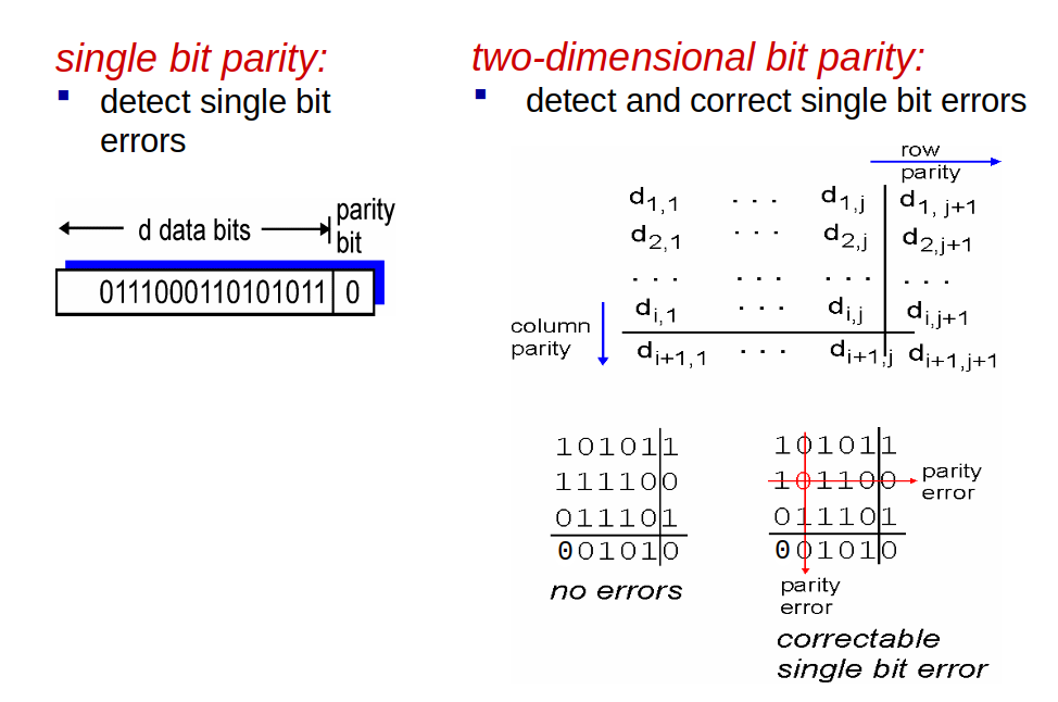
# Parity Checking
</img>
---
# Parity Checking
 </img>
---
# Error Detection – Checksum
### The sender:
1. Data is divided into k segment each of m bits (normally 16-bits integers) and summed.
3. The 1s complement of the sum forms the checksum
4. The checksum segment is sent along with the data segments
---
# Error Detection – Checksum
### Sending four segments:
- k = 4 m=8
- Segment #1 1 0 1 1 0 0 1 1
- Segment #2 1 0 1 0 1 0 1 1
- Segment #3 0 1 0 1 1 0 1 0
- Segment #4 1 1 0 1 0 1 0 1
---
# Error Detection – Checksum
- 10110011 segment #1
- 10101011 segment #2 XOR them
----
- 01011110 ( 1 carry over)
----
- 01011111 sum
- 01011010 segment #3
----
- 10111001
- 11010101 segment #4
---
# Error Detection – Checksum
----
- 10001110 ( 1 carry over)
----
10001111 sum
----
01110000 Checksum
---
# Error Detection – Checksums
### The receiver:
1. All received segments are added
2. The sum is complemented
3. If the result is zero, the received data is OK; otherwise wrong
---
# Error Detection – Checksums
- 10110011 segment #1
- 10101011 segment #2
-----------------------------
- 01011110 ( 1 carry over)
-----------------------------
- 01011111 sum
- 01011010 segment #3
------------------------------
- 10111001
- 11010101 segment#4
--------------------------
- 10001110 (1 carry over)
---
# Error Detection – Checksums
--------------------------
- 10001111
- 01110000 Checksum
------------------------------
- 11111111 sum
- 00000000 complement
- Data is accepted
---
# Error Detection - CRC
</img>
---
# Error Detection – Checksum
### The sender:
1. Data is divided into k segment each of m bits (normally 16-bits integers) and summed.
3. The 1s complement of the sum forms the checksum
4. The checksum segment is sent along with the data segments
---
# Error Detection – Checksum
### Sending four segments:
- k = 4 m=8
- Segment #1 1 0 1 1 0 0 1 1
- Segment #2 1 0 1 0 1 0 1 1
- Segment #3 0 1 0 1 1 0 1 0
- Segment #4 1 1 0 1 0 1 0 1
---
# Error Detection – Checksum
- 10110011 segment #1
- 10101011 segment #2 XOR them
----
- 01011110 ( 1 carry over)
----
- 01011111 sum
- 01011010 segment #3
----
- 10111001
- 11010101 segment #4
---
# Error Detection – Checksum
----
- 10001110 ( 1 carry over)
----
10001111 sum
----
01110000 Checksum
---
# Error Detection – Checksums
### The receiver:
1. All received segments are added
2. The sum is complemented
3. If the result is zero, the received data is OK; otherwise wrong
---
# Error Detection – Checksums
- 10110011 segment #1
- 10101011 segment #2
-----------------------------
- 01011110 ( 1 carry over)
-----------------------------
- 01011111 sum
- 01011010 segment #3
------------------------------
- 10111001
- 11010101 segment#4
--------------------------
- 10001110 (1 carry over)
---
# Error Detection – Checksums
--------------------------
- 10001111
- 01110000 Checksum
------------------------------
- 11111111 sum
- 00000000 complement
- Data is accepted
---
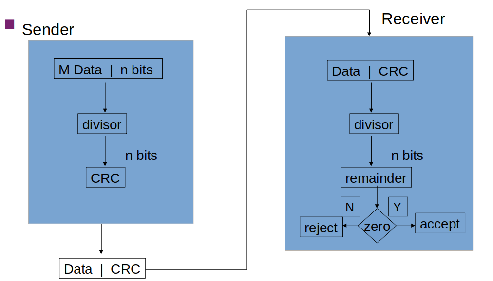
# Error Detection - CRC
 </img>
---
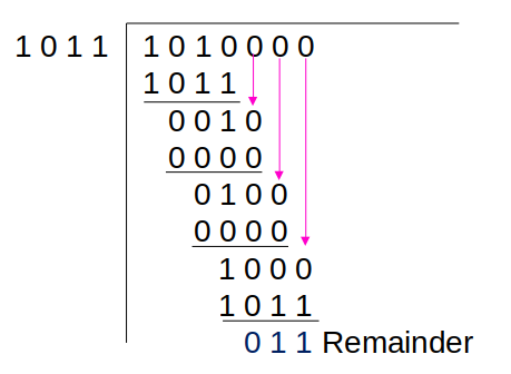
# Error Detection – CRC (example)
#### Example: encoding / sender side
M1 = 1 0 1 0</br>
P1 (Divisor) = 1 0 1 1
#### Generate CRC:
1. Add the degree of P1 (P1 length – 1) to M1 as zeros </br> P1 length - 1 = 4 – 1 = 3
2. Add 3 zeros to M1 </br> 1 0 1 0 0 0 0
3. Divide M1 by P1 using XOR
---
# Error Detection – CRC (example)
Transmitted frame: 1 0 1 0 0 1 1
</img>
---
# Error Detection – CRC (example)
#### Example: encoding / sender side
M1 = 1 0 1 0</br>
P1 (Divisor) = 1 0 1 1
#### Generate CRC:
1. Add the degree of P1 (P1 length – 1) to M1 as zeros </br> P1 length - 1 = 4 – 1 = 3
2. Add 3 zeros to M1 </br> 1 0 1 0 0 0 0
3. Divide M1 by P1 using XOR
---
# Error Detection – CRC (example)
Transmitted frame: 1 0 1 0 0 1 1
 </img>
---
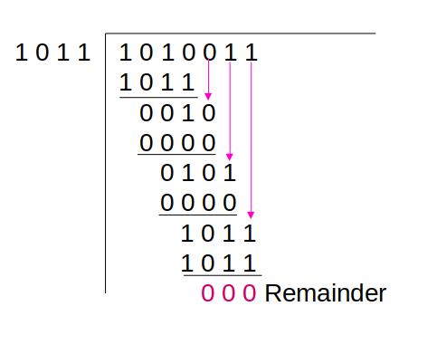
# Error Detection – CRC
#### Example: decoding / receiver side
Message: 1 0 1 0 0 1 1
Divisor: 1 0 1 1
- Divide the received message by the divisor
- If the result is 0, message is correct. Otherwise, message is incorrect.
---
# Error Detection – CRC (example)
</img>
---
# Error Detection – CRC
#### Example: decoding / receiver side
Message: 1 0 1 0 0 1 1
Divisor: 1 0 1 1
- Divide the received message by the divisor
- If the result is 0, message is correct. Otherwise, message is incorrect.
---
# Error Detection – CRC (example)
 </img>
---
# Summary
- Link layer services
- Data Framing
- Error detection and correction
</img>
---
# Summary
- Link layer services
- Data Framing
- Error detection and correction