Anne Reinarz Durham University
MAC Layer
MAC Layer
Outline
- Elements of wireless network
- Wireless links, characteristics, and types
- IEEE 802.11 wireless LANs (“Wi-Fi”) and features
- Signals
- Hidden and exposed terminal
- Wireless LAN standards & architecture
- Channeling, association and scanning
- IEEE 802.11 MAC protocol
- CSMA/CA
- IEEE 802.11 framing
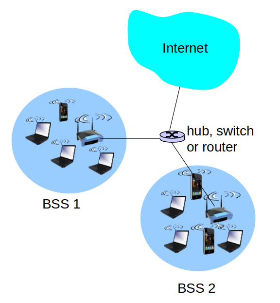
802.11 LAN architecture
 </img>
- Wireless host communicates with base station
- Base station = access point (AP)
- Basic Service Set (BSS) (aka “cell”) in infrastructure mode contains:
- Wireless hosts
- Access point (AP): base station
- Ad hoc mode: hosts only
802.11: Channels, association
- 802.11b: 2.4GHz-2.485GHz spectrum divided into 11 channels at different frequencies
- AP admin chooses frequency for AP
- Interference possible: channel can be same as that chosen by neighboring AP!
802.11: Channels, association
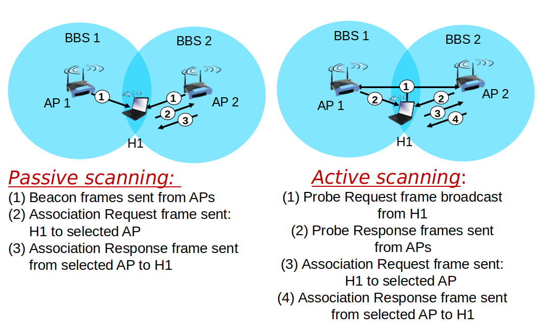
- Host must associate with an AP
- Scan channels, listening for beacon frames containing AP’s name (SSID) and MAC address
- Selects AP to associate with
- May perform authentication
802.11: passive/active scanning
 </img>
IEEE 802.11: multiple access
- Avoid collisions: 2+ nodes transmitting at same time
- 802.11: CSMA - sense before transmitting
- Don’t collide with ongoing transmission by other node
IEEE 802.11: multiple access
- 802.11: no collision detection!
- Difficult to receive (sense collisions) when transmitting due to weak received signals (fading)
- Can’t sense all collisions in any case: hidden terminal, fading
- Goal: avoid collisions: CSMA/C(ollision)A(voidance)
IEEE 802.11 MAC Protocol: CSMA/CA
802.11 sender
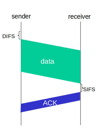
- If sense channel idle for DIFS (Distributed Inter-Frame Space)
- then transmit entire frame (no CD)
- If sense channel busy then
- start random backoff time
- timer counts down while channel idle
- transmit when timer expires
- if no ACK, increase random backoff interval, repeat step 2.
IEEE 802.11 MAC Protocol: CSMA/CA
802.11 receiver
- If frame received OK
- return ACK after SIFS (Short Inter-Frame Space)
- ACK needed due to hidden terminal problem)
IEEE 802.11 MAC Protocol: CSMA/CA
 </img>
Avoiding collisions
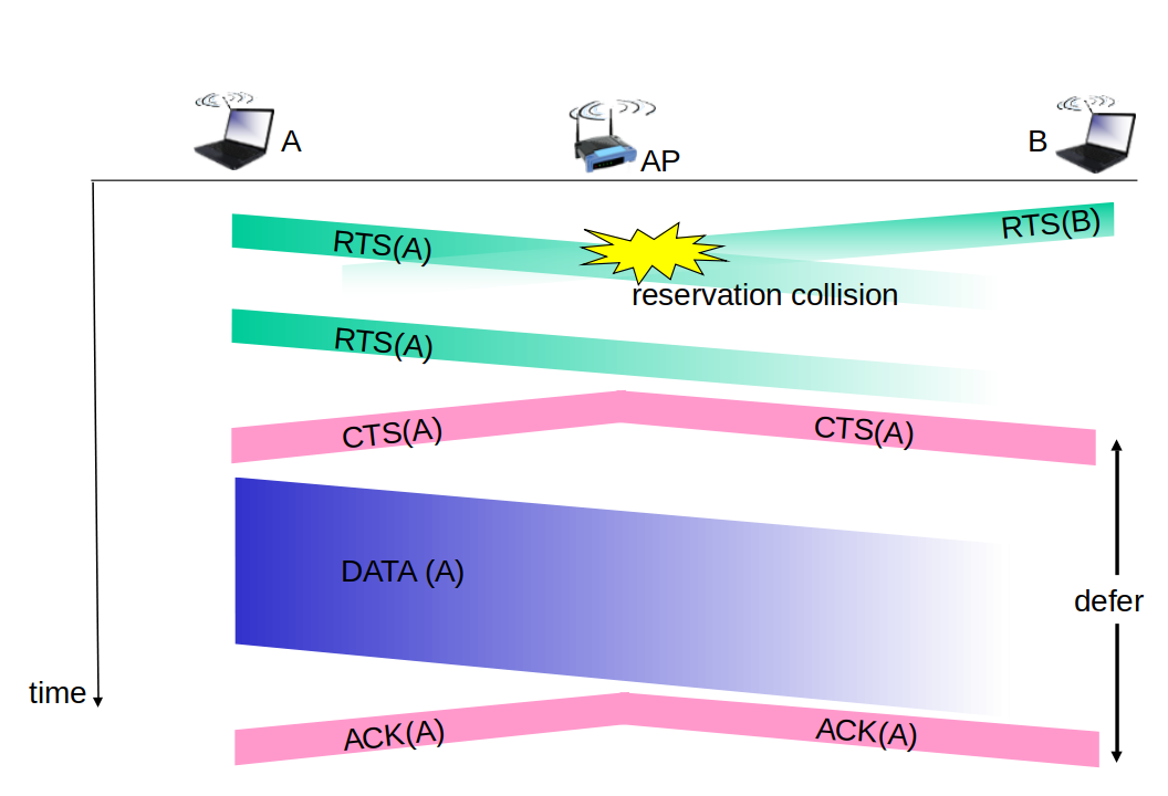
Idea: allow sender to “reserve” channel rather than random access of data frames: avoid collisions of long data frames
Avoiding collisions
- Sender first transmits small request-to-send (RTS) packets to BS using CSMA
- RTSs may still collide with each other (but they’re short)
- BS broadcasts clear-to-send CTS in response to RTS
- CTS heard by all nodes
- Sender transmits data frame
- Other stations defer transmissions
Collision Avoidance: RTS-CTS exchange
 </img>
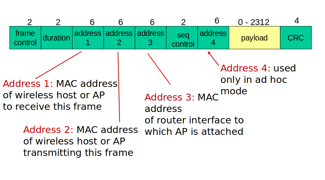
802.11 frame: addressing
 </img>
Physical Layer
Outline
- Bandwidth of signals and channels
- Digital modulation schemes (NRZ, NRZI, Manchester etc.)
- Multiplexing
Bandwidth
Two distinct senses:
- Synonymous with “bit rate” (rate of data transmission)
- E.g. 10Mbps
- Width of a range of frequencies (e.g. as used by a signal)
- E.g. 0 Hz through 10 MHz (10 MHz bandwidth)
- E.g. 20 MHz through 30 MHz (10 MHz bandwidth)
Bandwidth
- Baseband: a range running from 0 to some maximum frequency. Typically applicable to wired media.
- Passband: signals occupying some range of frequencies, as would pass through corresponding frequency filters.
- E.g. 802.11b channel #3: 2.411GHz ~ 2.433GHz
- Channel has bandwidth of: 2.433-2.411 GHz = 22 MHz
- “Available” bandwidth
- Range of frequencies usefully transmissible in a medium
- A physical property of the transmission medium
Digital Signals
- 0s and 1s may take on many possible representations when transmitted
- Some representations have desirable properties for particular media
Digital signals are obtained from an analog signal:
Information transmitted by varying some physical property such as voltage or current
Digital Modulation
- Digital signals (0, 1) are encoded by (e.g.) low and high voltage
- Digital Encoding Schemes:
- Non-Return-to-Zero (NRZ)
- Non-Return-to-Zero-Inverted (NRZ-I)
- Bipolar encoding, a.k.a. Alternate Mark Inversion (AMI)
- Manchester encoding
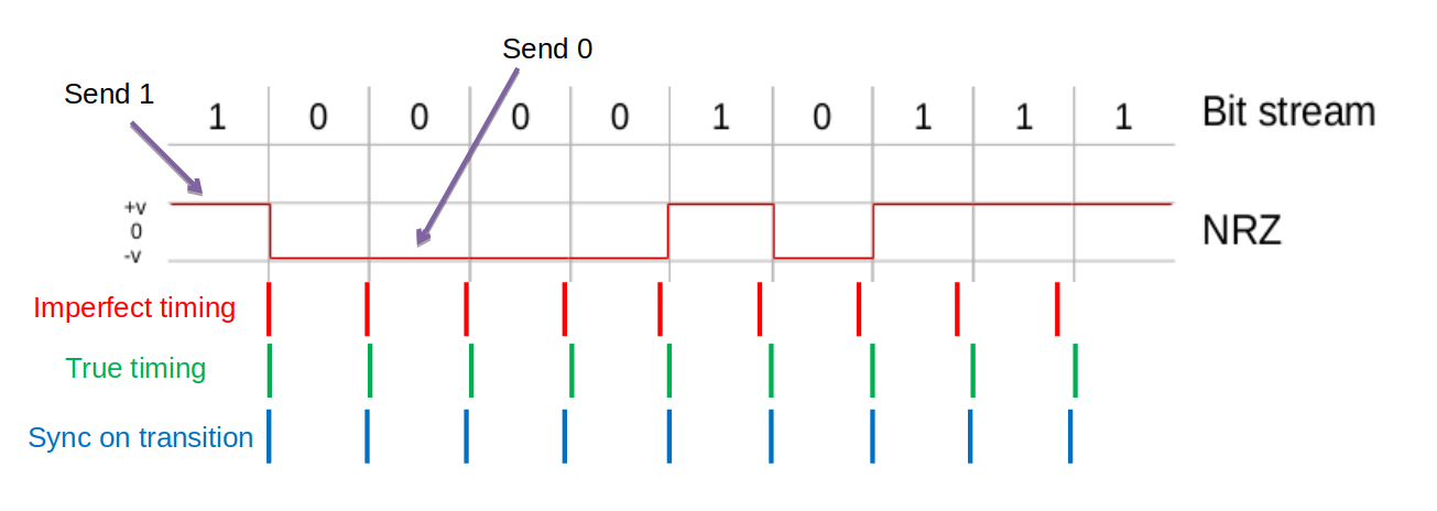
1. NRZ Encoding
- A high voltage represents a 1
-
A low voltage represents a 0
- The name NRZ refers to the fact the voltage does Not Return to Zero, it changes only when the bit value changes
1. NRZ Encoding
 </img>
1. NRZ Encoding
- Relies on sender and received having accurate, in sync “clocks”
- Transitions (from +v to -v, or -v to +v) can be used to correct small deviations
- Problem: long runs of consecutive bits with same value [no changes in voltage] the constant signal values cannot synchronize the communicating devices
- Various other schemes offer possible solutions to this problem (recall: bitstuffig)
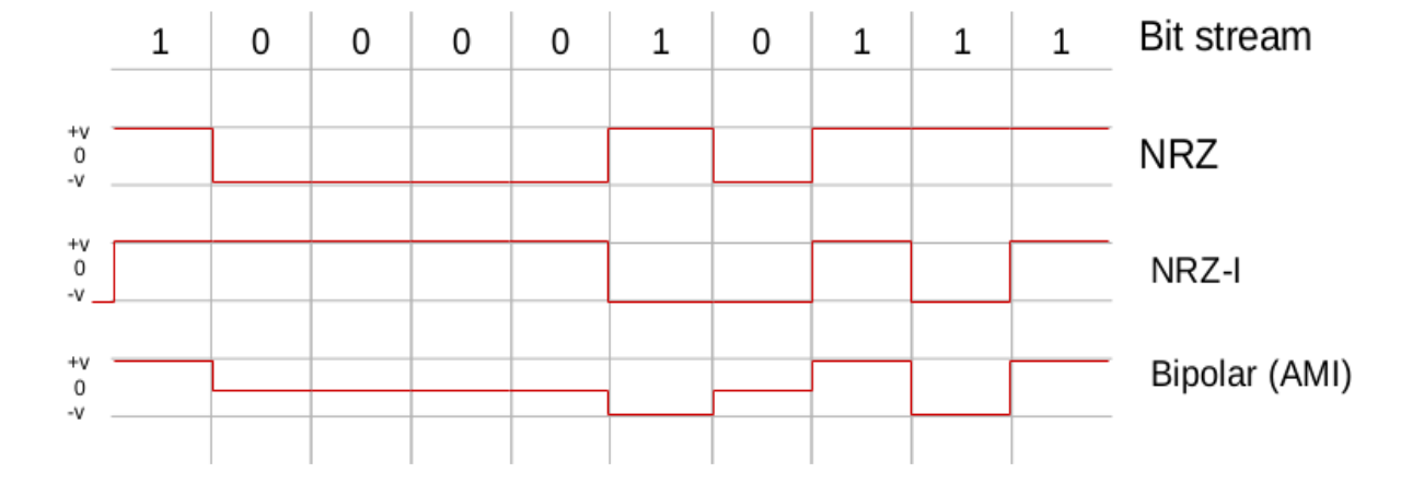
2. NRZI (inverted) Encoding
- NRZI attempts to alleviate the problem in NRZ
- ‘0’ is encoded as no change in the level
- ‘1’ is encoded depending on the current state of the line.
- If the current state is low voltage the ‘1’ will be encoded as a high voltage, if the current state is again high voltage the ‘1’ will be encoded as a low voltage
2. NRZI (inverted) Encoding
 </img>
- This fixes the problem of sending consecutive 1s but not consecutive 0s
3. Bipolar Encoding
- 0 is represented by a zero voltage, neither high nor low.
- 1 is represented by either positive voltage or negative voltage.
- Chosen voltage inverted from the last transmission of 1
- I.e. represented by a negative voltage if it was represented by a positive voltage when it was last transmitted, and vice versa
3. Bipolar Encoding
 </img>
- “Balanced encoding”
- sum voltage 0
- desirable in some applications
4. Manchester Encoding
- Merge an explicit clock signal with the data signal
- Use XOR to merge the two
- Low-to-high voltage transition represents 1
- High-to-low voltage transition represents 0
- Inverse of this convention is sometimes used
4. Manchester Encoding
 </img>
4. Manchester Encoding
-
Uses signal changes to transmit data and achieve synchronization
-
Guaranteed transitions – occur with each bit transmitted
-
Problem: Twice the bandwidth of NRZ is required
Multiplexing
Multiplexing
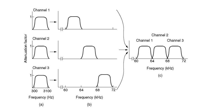
- Channels are often shared by multiple signals
- Different ways to accomplish multiplexing:
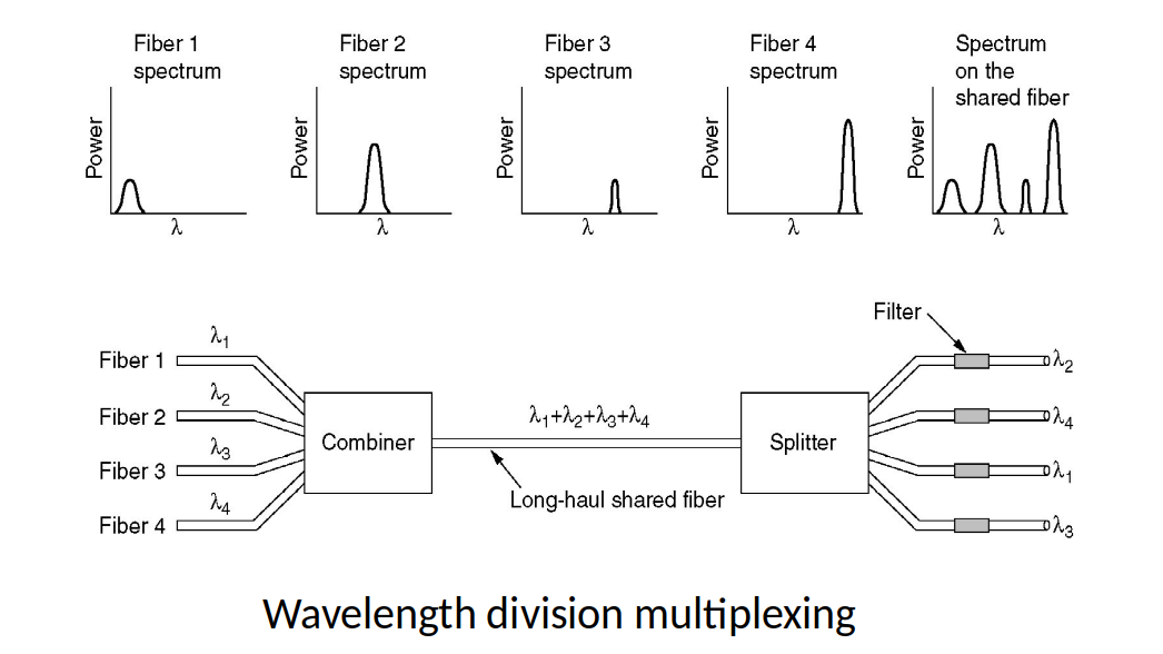
- FDM (Frequency Division Multiplexing)
- WDM (Wavelength Division Multiplexing)
- TDM (Time Division Multiplexing)
- CDMA (Code Division Multiple Access)
Frequency Division Multiplexing
 </img>
Wavelength Division Multiplexing
 </img>
Time Division Multiplexing
 </img>
CDMA – Code Division Multiple Access
- Method allowing every transmitter to use the entire channel all the time
- Individual transmissions are extracted by a receiver using coding theory
- Channel itself merges the transmissions
CDMA – Code Division Multiple Access
- Suppose we have four transmitters called, from now on, stations
- Each station has a “chip” (i.e. code), which is a four-bit vector, e.g.:
- A : (+1 +1 +1 +1)
- B : (+1 −1 +1 −1)
- C : (+1 +1 −1 −1)
- D : (+1 −1 −1 +1)
- These “chips” are chosen so that they are all orthogonal to one another:
- A · B = 0, B · A = 0, … A · C = 0, …
CDMA – Code Division Multiple Access
- For mathematical simplicity, we will call the two binary states -1 and +1
- Stations transmit data by transmitting either:
- Their chip sequence, to transmit a 1
- The negation of their chip sequence, to transmit a -1
- Nothing at all if they do not wish to transmit
CDMA – Code Division Multiple Access
- A : (+1 +1 +1 +1)
- B : (+1 −1 +1 −1)
- C : (+1 +1 −1 −1)
- D : (+1 −1 −1 +1)
- For instance, in this example:
- B can transmit a +1 data value by transmitting: +1, -1, +1, -1
- B can transmit a -1 data value by transmitting: -1, +1, -1, +1
Summary
- Bandwidth of signals and channels
- Digital modulation schemes (NRZ, NRZI, Manchester, etc.)
- Multiplexing (FDM, TDM, WDM, and CDMA)